DIY : How to increase airflow to your stock throttle body


HondaNickx

Member
Joined
Jan 7, 2010
Messages
166
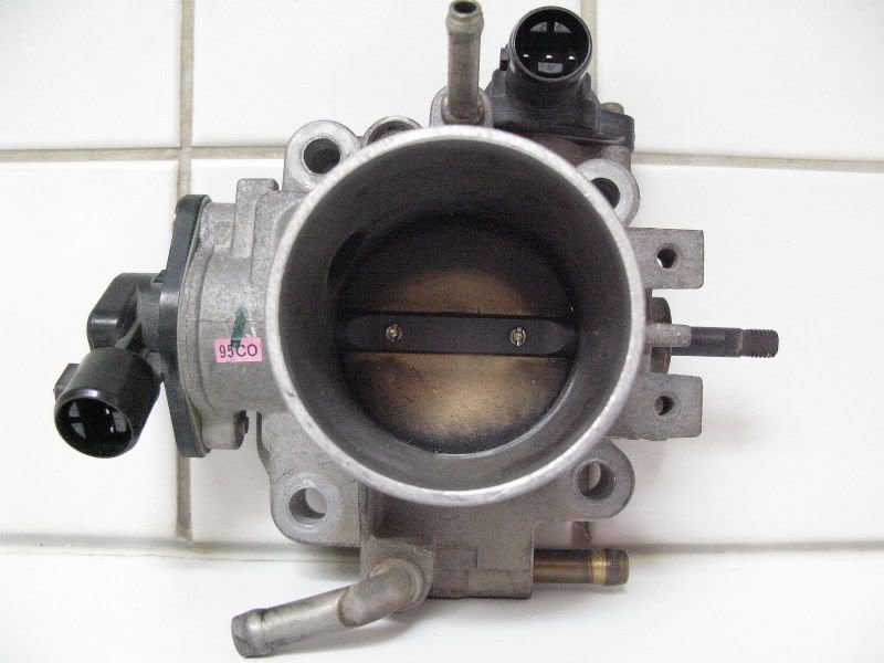
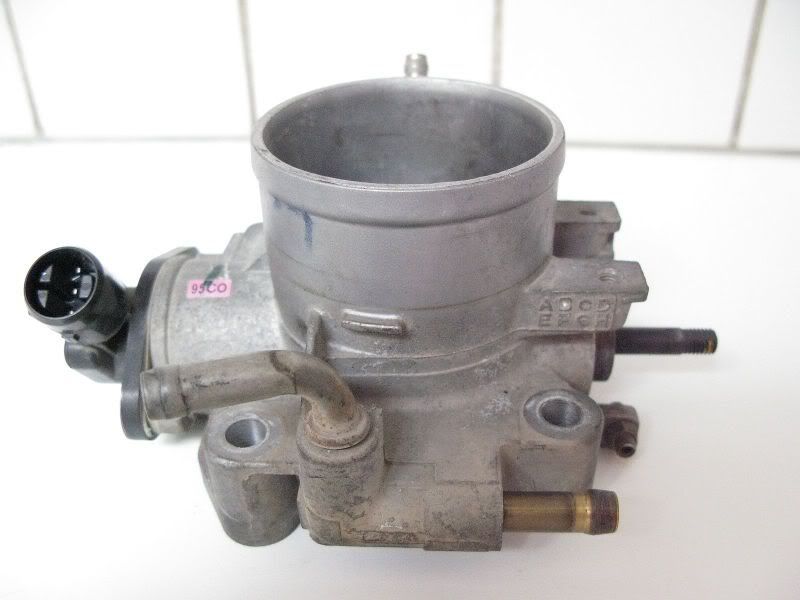
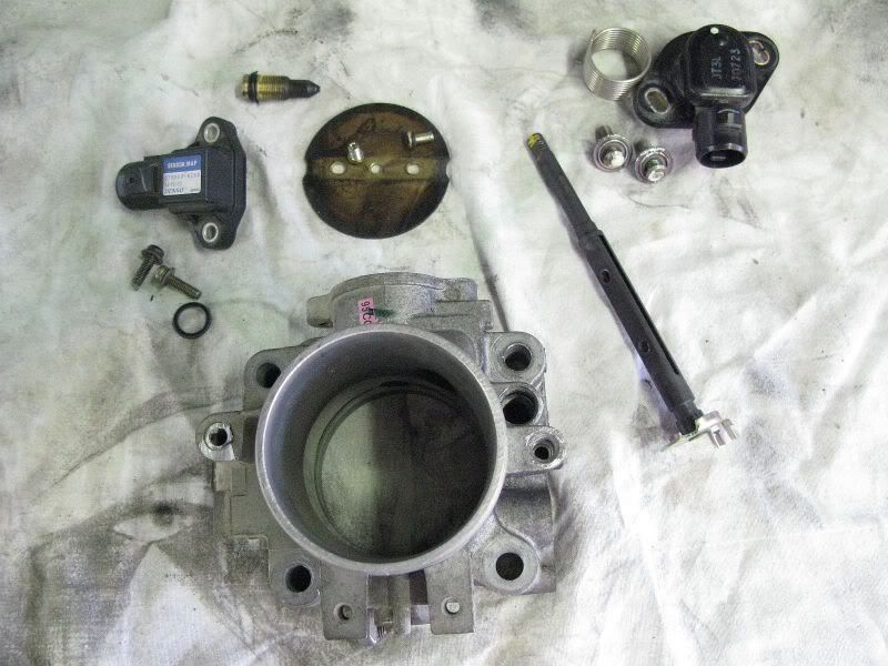
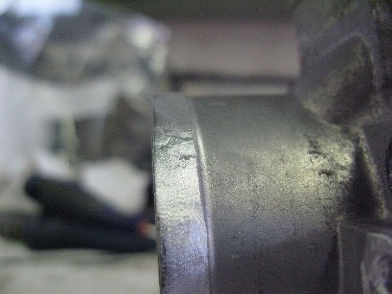
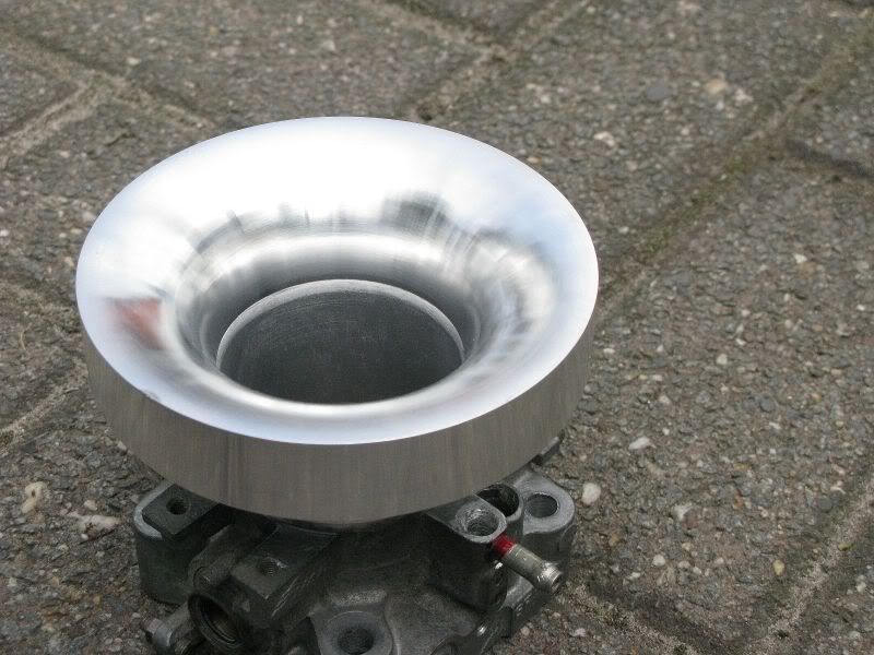
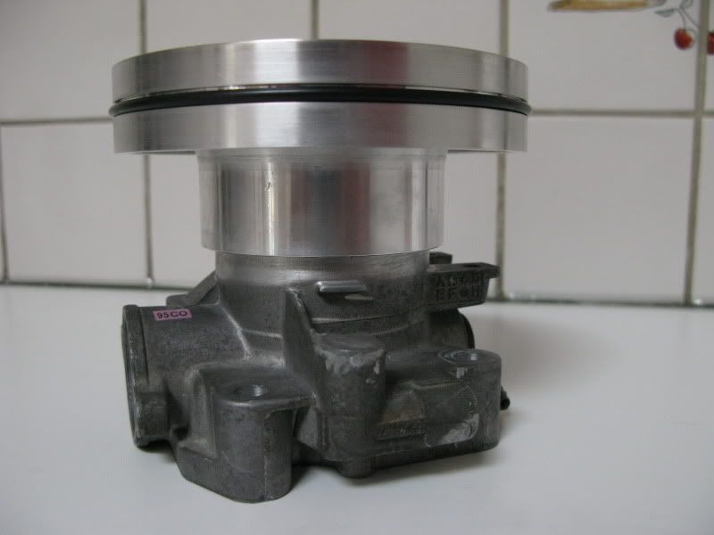
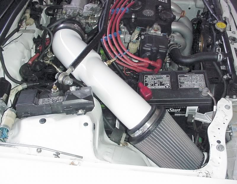
This is something i did a while ago .This topic has lot's of pages on a other forum so i'll just post the most important stuff here ;) .It applies to a D-series Throttle body but it works on any throttle body that has a butterfly valve.


img6300qx5.jpg

img6327fd4.jpg

img6349xu0.jpg

img6293jk5.jpg

img6320xu8.jpg

img6294fb6.jpg

img6290jd4.jpg

img6278ym5.jpg

img6302ep5.jpg

img6316kt5.jpg

img6313jl7.jpg

img6319zb4.jpg

img6354qk0.jpg

img6355bk4.jpg

img6353fj9.jpg


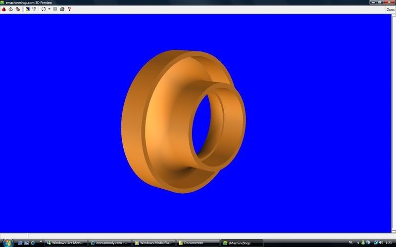
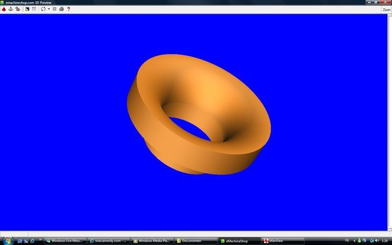
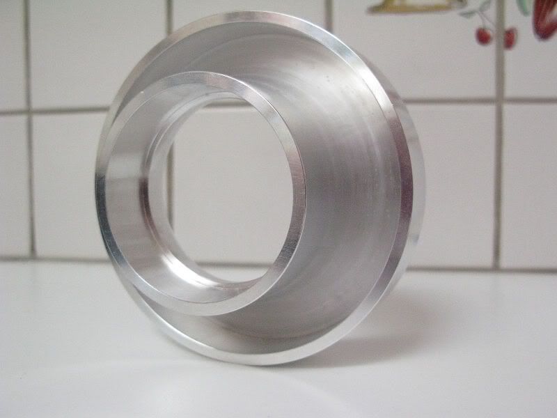
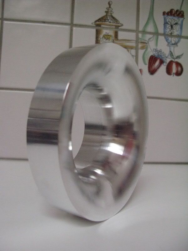
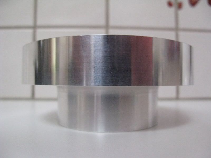
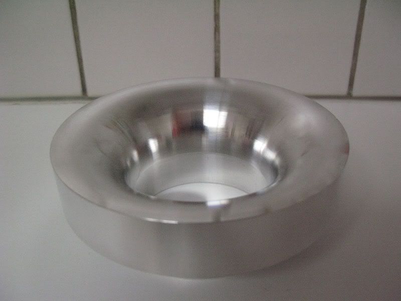
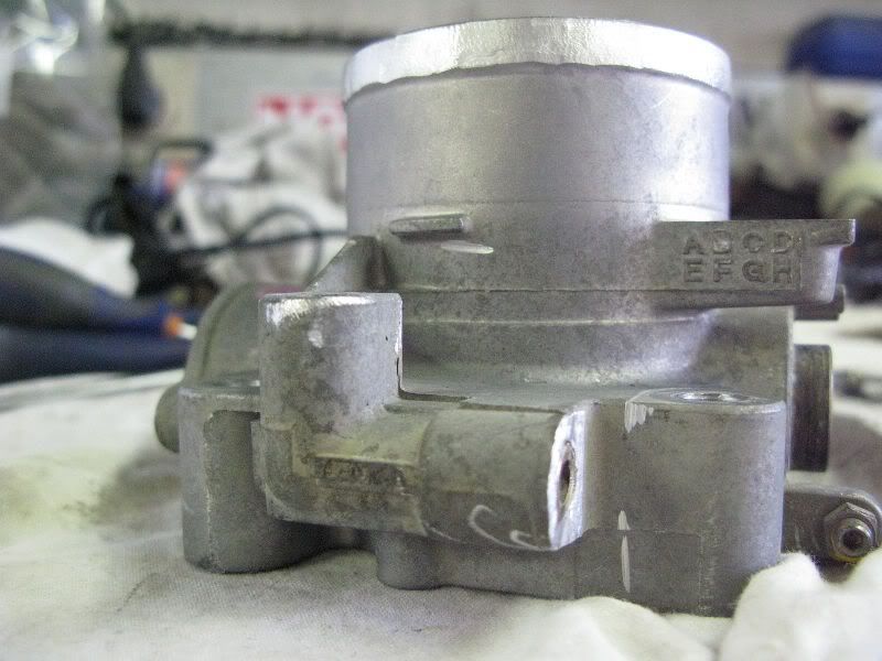
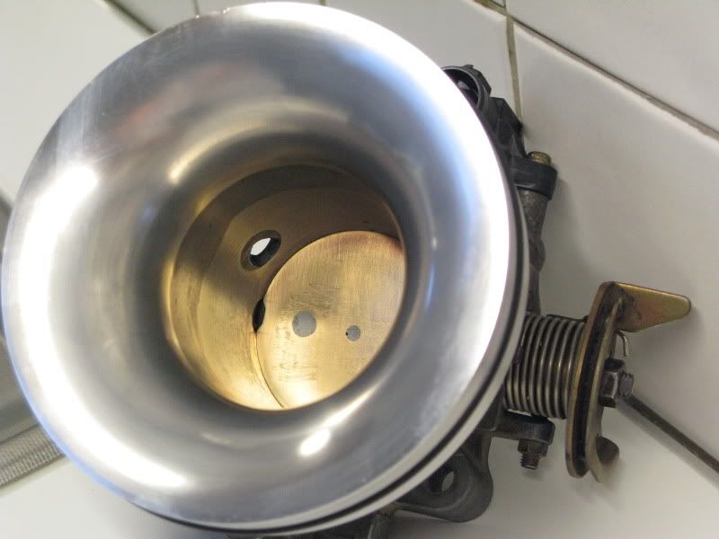
I used Endyn 's archive for the radius and intake calculating and offcourse lots of tips from Rushi for the Tb.Quote from Larry “Using this formula's radius combined with the 25% increase in area in front of the throttle body allows the lower velocity air flow in the inlet "tube" to exert considerable pressure on the throttle body which is highly desirable from a power standpoint.”

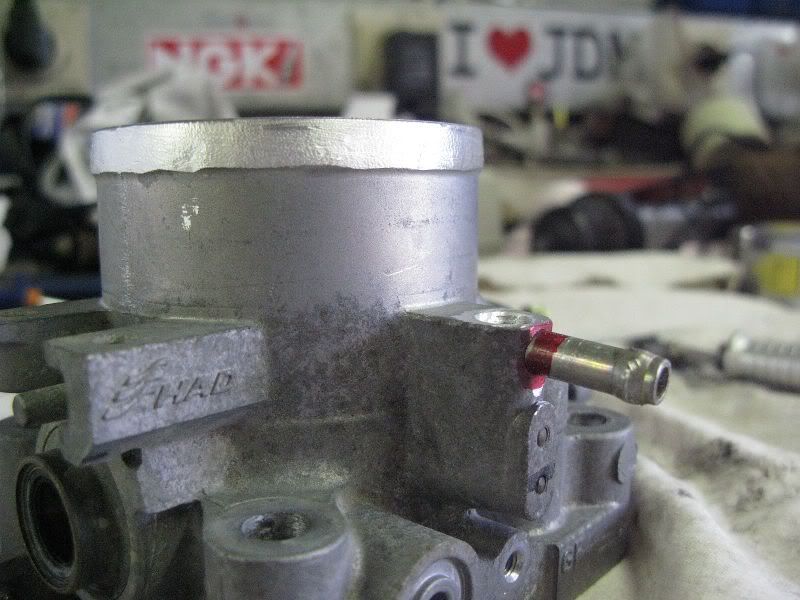
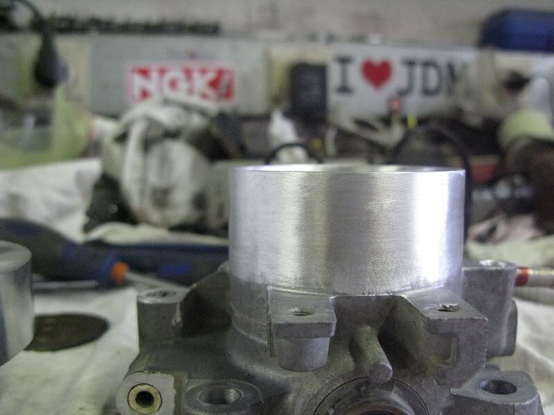
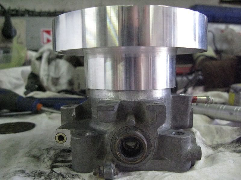
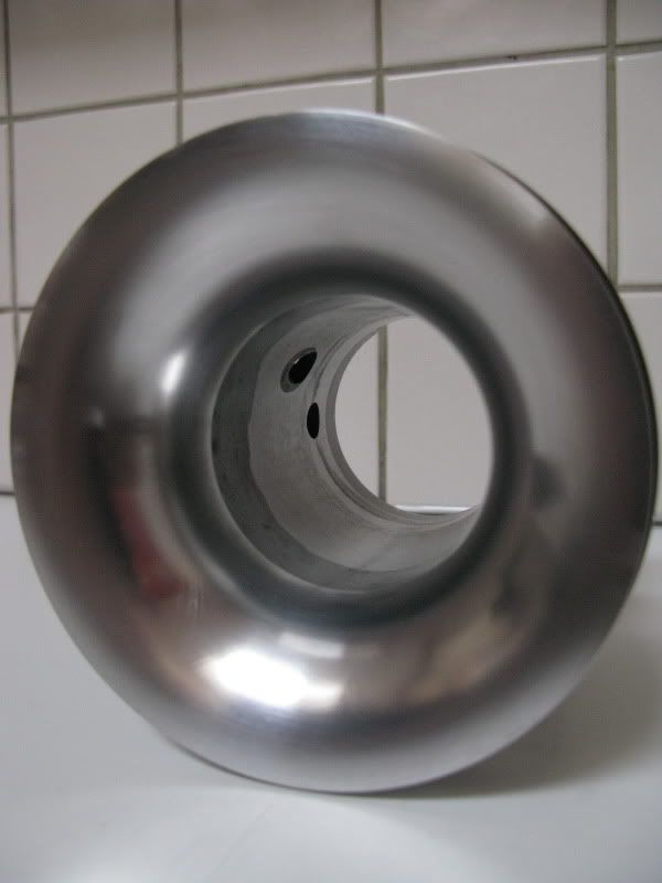
I also noticed Larry said to make a Radiused connection wherever possible by using the formula 1/2 of the TB diameter.

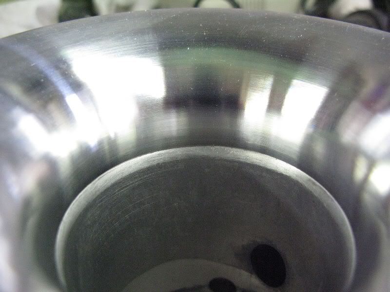
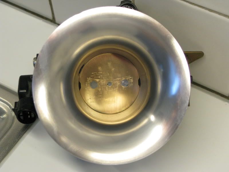
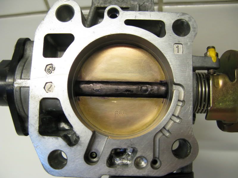
For the throttle shaft i used a method from the book "4 Stroke tuning" from A. Graham Bell.He said there could be gained 10-12% in flow by reducing the shaft thickness ,removing the screws and cutting 1 side away.Other then that i've read on a Skyline forum that some company's used paint for Rc cars to seal the Tb.The trick here was to apply a very thin coating of paint with the butterfly shut.I used Motip white tire marker for this .I had this laying around and i think it will work thesame since it both flexibel paint .I later discovered moly based paint is what they use in OEM TB's.

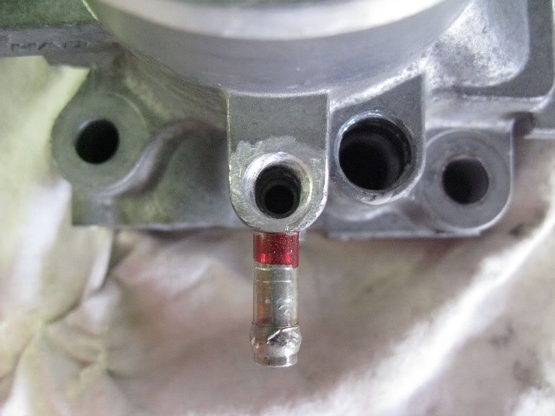
Note: This was my first design and later i discovered i miscalculated the Radius and actually used half the radius i supposed to use.
 
Last edited:
So i went back to the drawing boards and made a new radius adaptor piece.The stock D-series tb tapers down from 60mm to 55mm of the butterfly.

The new radius adaptor is going to be 120mm in diameter with a radius of R= 30mm.

Velocitystack01.jpg


Velocitystack02.jpg


Allright guys i received my radius adaptor today ,and i allready got started on my new TB.Btw this things looks Awesome E-Machineshop did a fantastic job making this :bowdown:.

001.jpg

002.jpg

003.jpg

004.jpg


The Donor Throttle body ( D16Y8 )
005.jpg

006.jpg


Dissambly
007.jpg


Removing coolant passage tubes (i'm not using those)
008.jpg


Reworked the little tube sticking up (in the way of the Tb radius)
I think this is for somekind of idle ,not sure how to hook it up yet.
009.jpg

010.jpg


This bump needs to be removed with a grinder/dremel so the TB radius can slide over.
011.jpg

012.jpg


And yes a perfect fitment
013.jpg

014.jpg

015.jpg


The seem will be filled with defcon later

IMG_3605.jpg


IMG_3606.jpg


IMG_3612.jpg


IMG_3613.jpg


IMG_3614.jpg
 
This is how Endyn (Larry) made his model many many years ago on his n/a D16a6 back then .
New_MegaTube_Endyn.jpg


New_MegaTube_Endyn02.jpg


New_MegaTube_Endyn03.jpg


New_MegaTube_Endyn04.jpg


New_MegaTube_Endyn05.jpg


This is also their first intake tube design.Later one they made a new design which tapered over the entire length of the tube.
 
Nice:nice: Did it make much difference to power when fitted back on?
 
I still didn't had a chance of really testing it .By that i mean going onto a dyno and doing back to back runs of the stock and modified TB.I'm still waiting till i get all of my parts together and finally swap the entire head ,intake manifold ,Tb and custom intake pipe.It might be a small gain on it's own ,but in the end all those small ones add up.
 
The velocity stack was made by Emachine shop in the usa.We did a little groupbuy over there to save costs to machine the adaptor.I made the drawings in the e-machine shop program though.
 
nice work man

make one for a b16b / b18c

id have one

well done
 
nice setup, usually people run the velocity stack right before the filter.
 
I'm using one on the entry on the intake pipe too.But most people don't even think about the most important transition from intake to Tb.If that transsition is messed up or not properly aligned your velocity stack at the entry of the intake pipe does only half the work or nothing at all.Even turbo bellmouths or podrams are a good thing to use.
 
What is a prodram? Is this another name for a velocity stack? I have seen nearly 20whp gained with the addition of a vstack on a turbo car, but that was a 600whp car...
 
Paint is hard to use cause it's not flexible enough and if you aply the paint too thick it will crack.My 2nd Tb seals up great without any sealant.
Honda uses molly based paint to do this .

A podram is a velocity stack where you can slide a filter over.Kinda like the Blox velocity stacks.I get all my velocity stacks from Velocityofsound.com

Velocity Stacks, Motorcycle Velocity Stacks (Ram Tubes or Air Horns) & Turbo Bellmouths

This is a podram
podrammedium1.jpg


And this is a bellmouth
tb2.jpg


mazdabellmouthlg.jpg


And a velocity stack for surrounding air(/ITB's,Carbs,...)
vs63-90.jpg


Podrams and bellmouths are more for ram air use.
ITB/Carbs velocity stacks are more for surrounding air use.

In the states there are even some people that are going to use the velocity stack on the tb with a turbo setup.I'm curious how that will work out for them.
 
i read that book too, second edition. very good read esp. on header topics.
can i see your TB shaft after you modify it? tapered screws would work nicely eh?
and does the moly paint chips after prolonged use?
how does it look after exposed to engine oil vapour and the build ups?

great job!
 
Awesome work. Already got a chance to dyno this?
 
Nice idea!

But I would think having the traditional Velocity stack > pipe runner > Venturi bored TB would perform best and is more practical.

There isnt any real air ram channeling in the setup. And it will be hard to dyno test it without ECU tuning. It wouldnt be a fair comparison as you might see the bottom end and mid range bog down badly. But I could be proved wrong. Goodluck with it!

I like this though. It would be perfect for the short runner velocity stack racing intake
img6354qk0.jpg
 
Nice work, but to be honest in order to truely get the venturi effect working there is a minimum length required based on a ratio with the diameter to be used and a few other calculations.

I am studying Mechanical Engineering and we've a uni race team where we've built a race car (weighting just a smig over 200kg) with an 07 R6 engine in it, we're taking it to silverstone in july to compete in an international competation but long story short....

we have designed and manufactured a venturi intake with a velocity stack fitted to the end, to be honest all the velocity stack does is help channel the air, it's actually the venturi section than cause's a differential in the air pressure, cause the air to speed up going through the bottle neck and in effect it create's its own vacuum, and hence pulls the air behind it in.

But in order for this to work a minimum air pressure is needed at the open/filter mouth and on the like's of your system this could only be achived with a sealed airbox with a healthy piped supply from the front bumper.

I'm currently working on an intake system for my EM1 which should if successful work on EK6 & 9's as well.
 
Last edited by a moderator:
Nice work, but to be honest in order to truely get the venturi effect working there is a minimum length required based on a ratio with the diameter to be used and a few other calculations.
I am studying Mechanical Engineering and we've a uni race team where we've built a race car (weighting just a smig over 200kg) with an 07 R6 engine in it, we're taking it to silverstone in july to compete in an international competation but long story short we have designed and manufactured a venturi intake with a velocity stack fitted to the end, to be honest all the velocity stack does is help channel the air, it's actually the venturi section than cause's a differential in the air pressure, cause the air to speed up going through the bottle neck and in effect it create's its own vacuum, and hence pulls the air behind it in.
But in order for this to work a minimum air pressure is needed at the open/filter mouth and on the like's of your system this could only be achived with a sealed airbox with a healthy piped supply from the front bumper.
I'm currently working on an intake system for my EM1 which should if successful work on EK6 & 9's as well.

Nice technical way of putting it. Most wont understand though.:nice:
 
Back
Top