
- Joined
- Apr 10, 2007
- Messages
- 2,876
PART 1
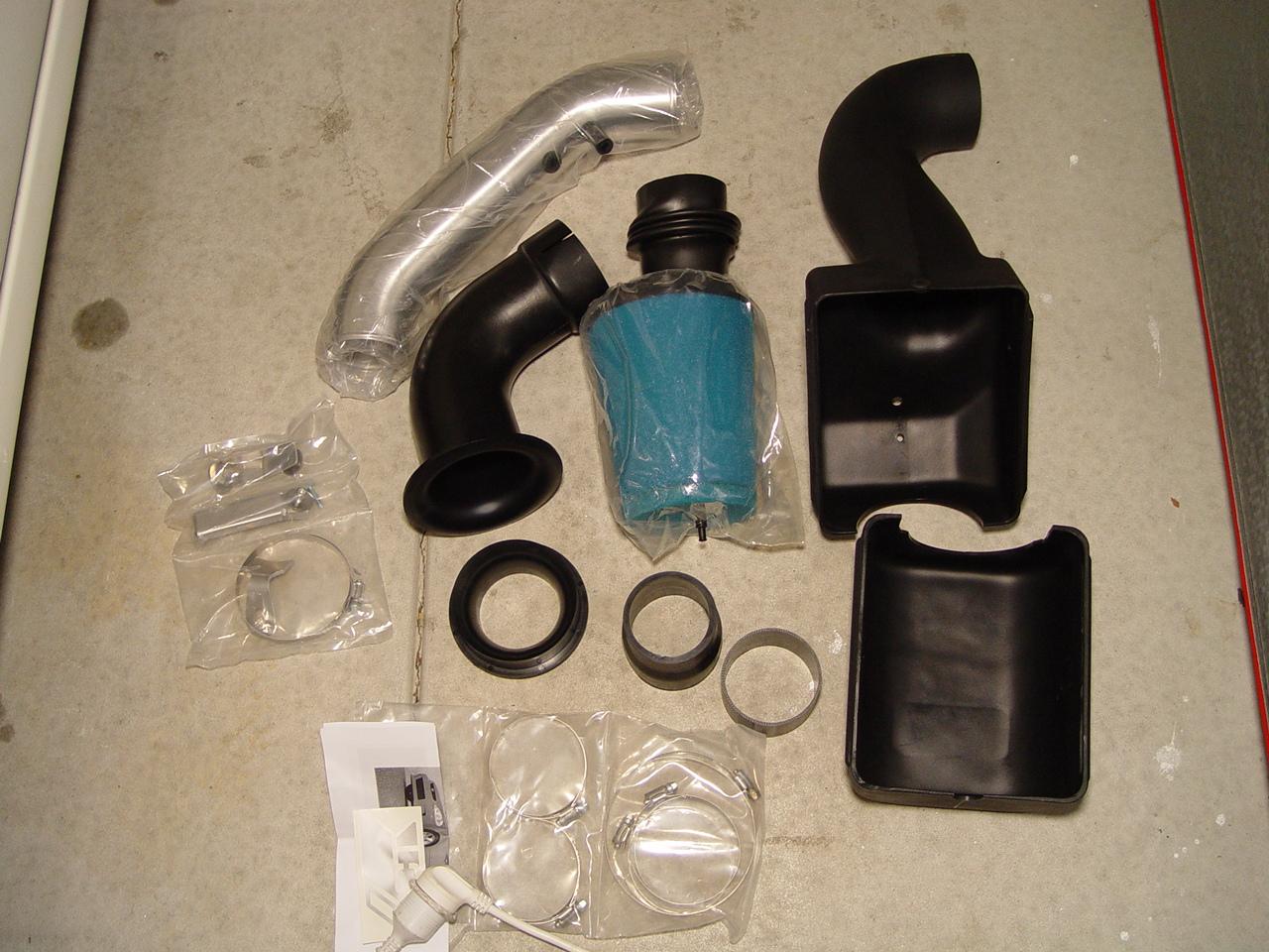
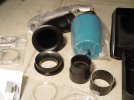
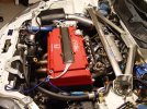
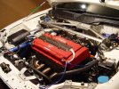
Ok, My final intake is here. My DIY Installation instructions should help those who have bought 2nd hand items since these are no longer in production. Although to this date, there are still a handful of NEW items left.
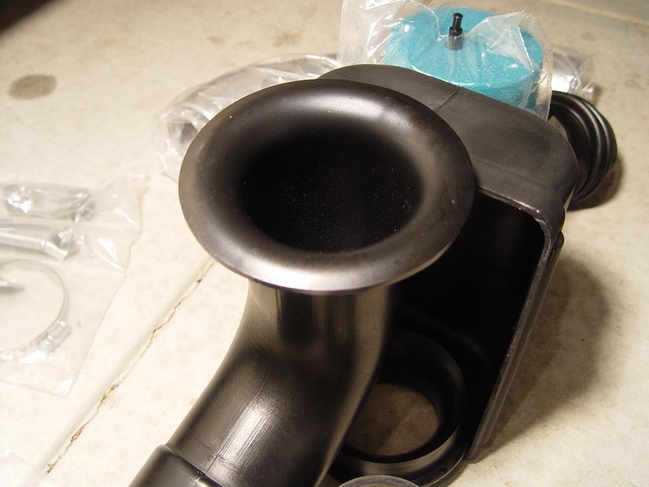
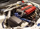
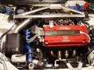
In short, the reason I chose this intake was for its efficiency, quieter and clean subtle stock look. The system also makes use of 2 velocity stacks.
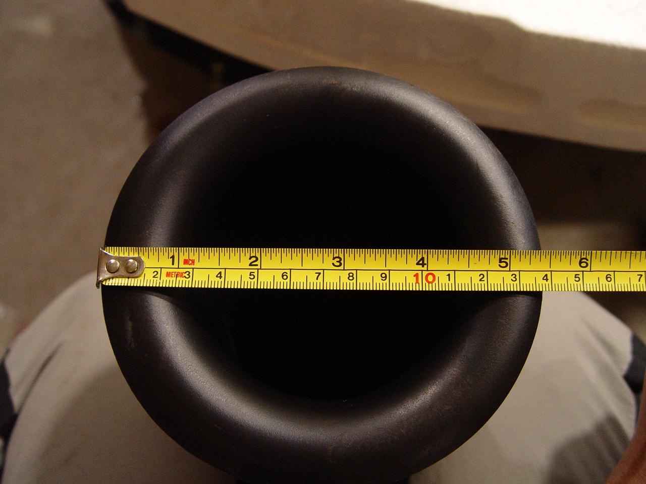
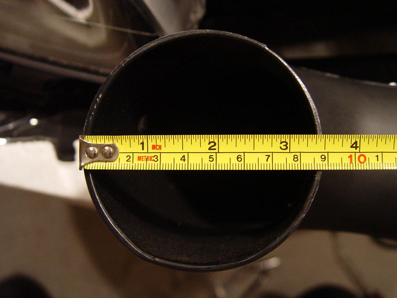
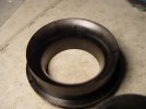
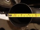
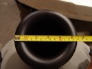
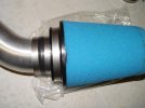
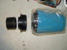
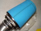
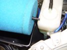
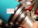
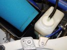
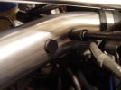
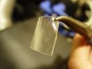
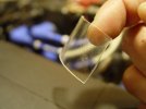
It is a 3.5" system throughout from the polished intake arm to the end of the ICE BOX which has a 5.5" velocity flare. Theres also an extra velocity stack that acts as a frame for the filter to tighten over. The filter is also quite big. A bit bigger than the stock DC2R.
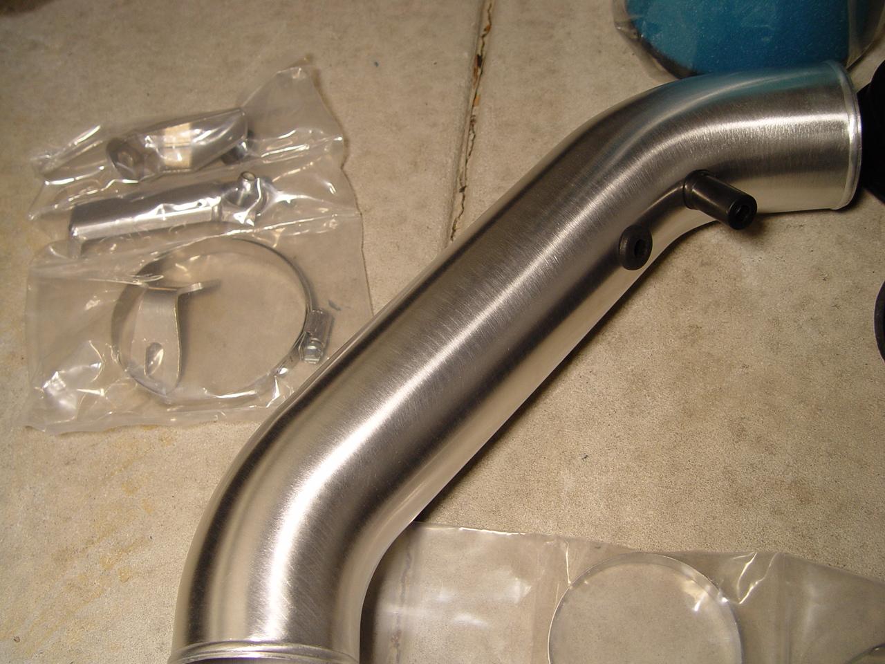
For best results, the polished Comptech aluminium intake arm should be used instead of the stock rubber arm, simply because the aluminium arm is smooth. The stock rubber arm has ripples inside the arm which in theory, affects flow. looking at the kit, Comptech really put lots of engineering into this intake.
I'll start with removing your old intake system. It is also manatory that you remove your front bumper for this install. It will also make things easy if you remove your front strut bar.
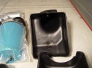
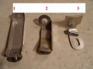
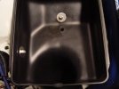
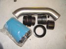
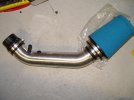
This is the kit;


Now I will label the brackets for the ICE BOX as #1,#2 and #3.

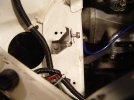
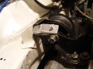
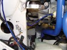
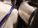
We will start by installing Bracket #3
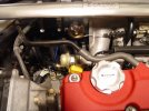
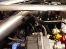
Look down next to the bottom of your radiator and hose.
You will see 3 large bolts tied down on the left wall.
Remove the one closest to the tranny to install the bracket #3
BUT, do not tighten the bolt, leave it loose as you will need to align it later before tightening.
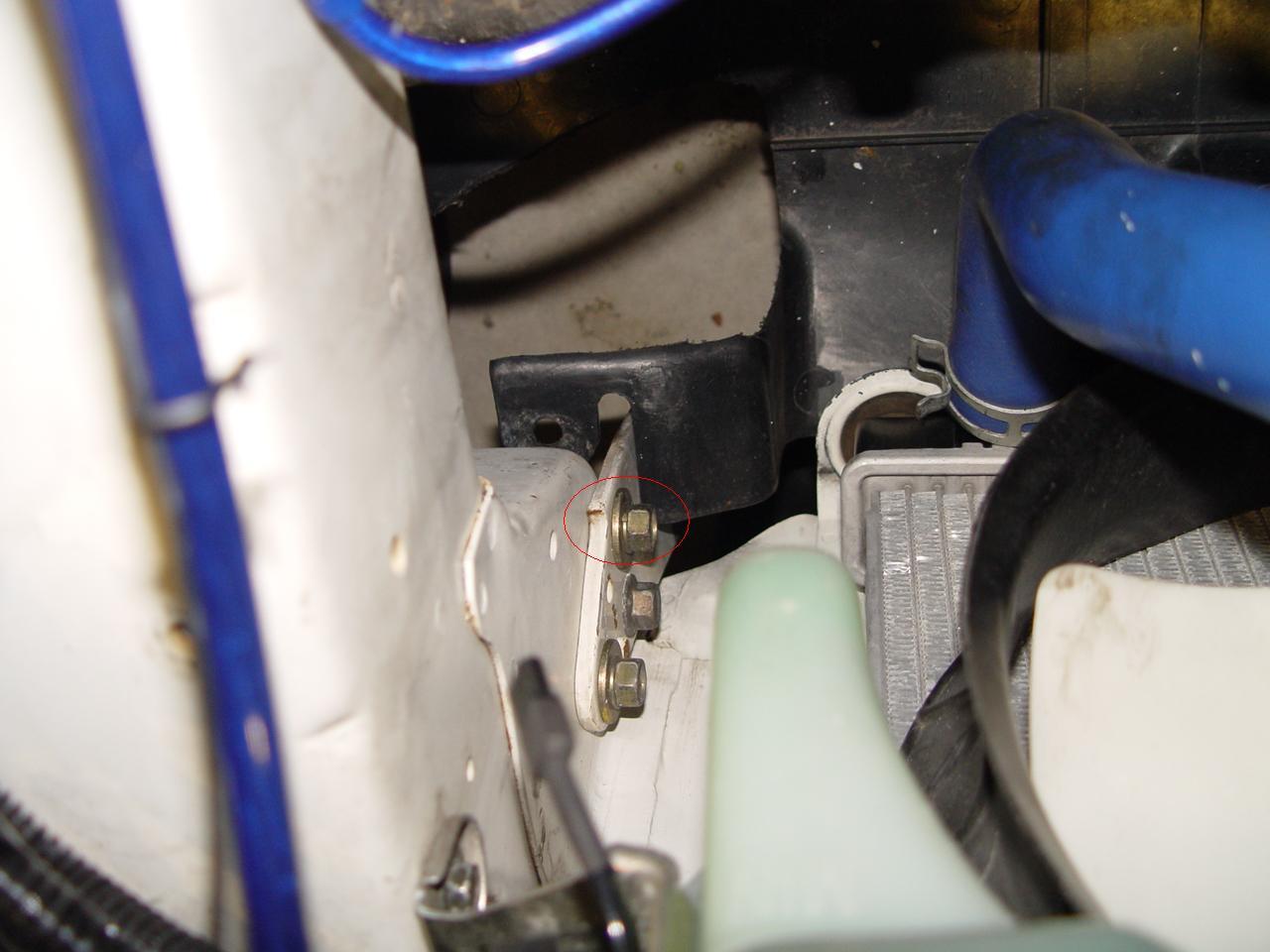
Like this...
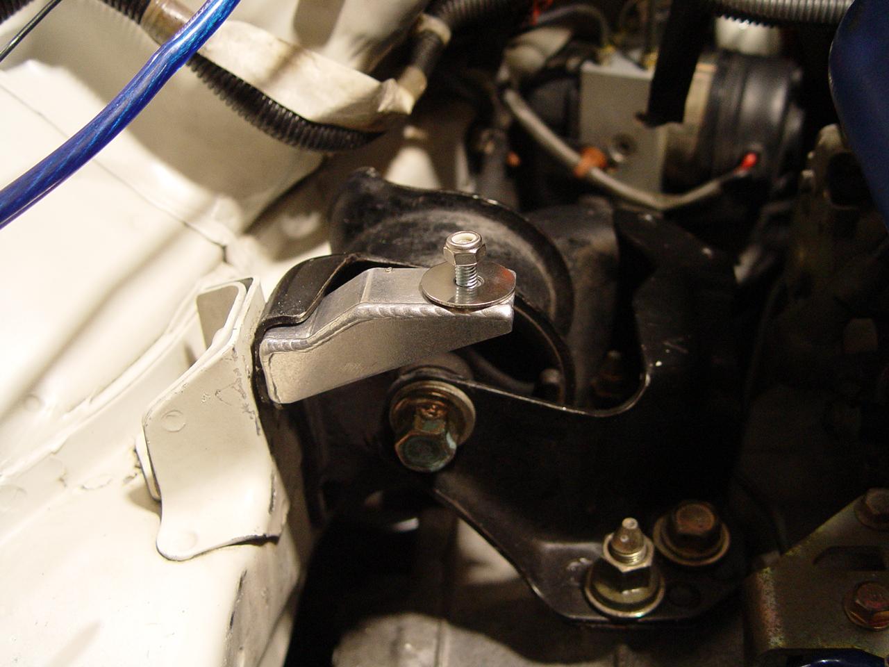
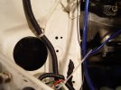
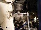
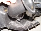
After that, we will install Bracket #2
Undo the tranny engine mount bolt that bolts to the side
Install the bracket and DO NOT tighten the bolt, just hand tight for now.
You will need to align the bracket angle later on.
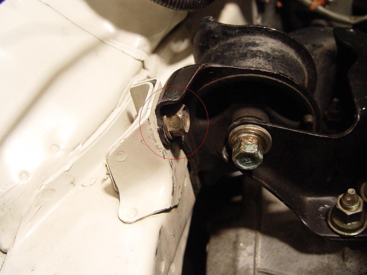
Like this...
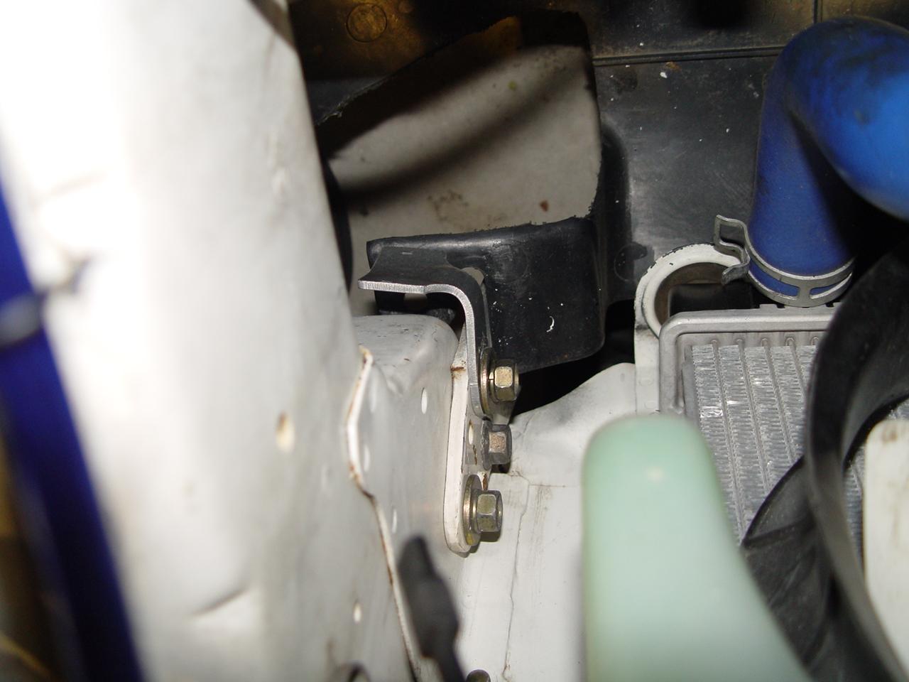
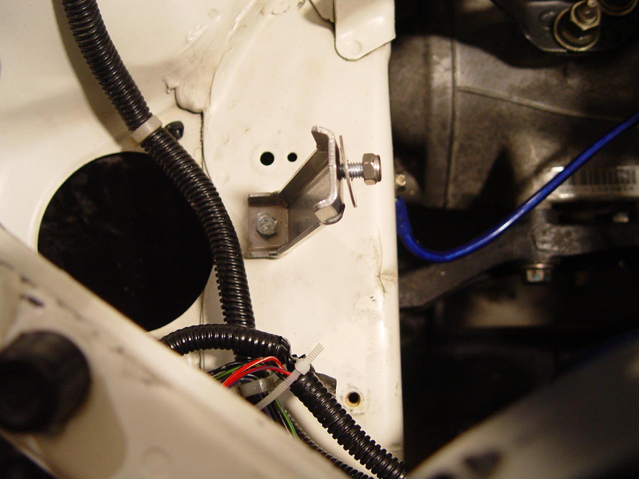
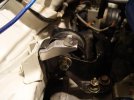
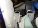
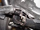
Next we install the last bracket #1
There should be a threaded hole here

Install the bracket and again, just hand tighten the bolts for later alignment.
like this...
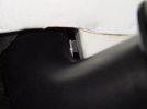
Once done it should look like this...

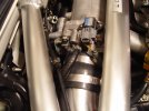
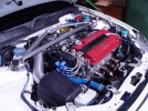
Now we fit the ICE BOX in to see how it aligns with the brackets...
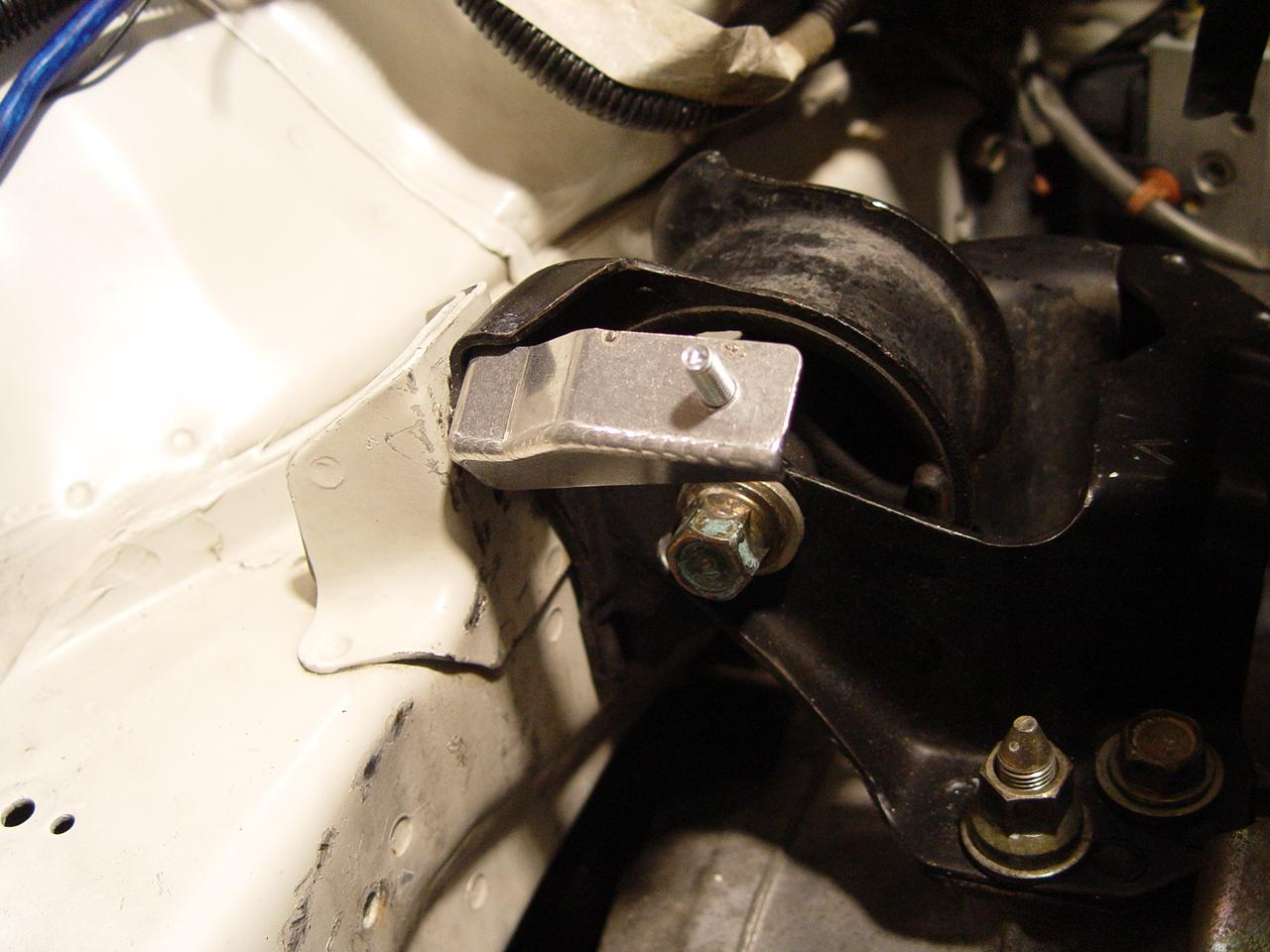
Bracket #2 will need to be aligned at 45degrees facing you for the ice box to fit.
Once the ICE BOX has sat on, dont bolt anything down yet.
Carefully the slowly take off the ICE BOX not to upset the Bracket #2s angle.
Fully tighten the bolt for Bracket #2 like this...

Put back the ICE BOX...
Hold down the ICE BOX by fully tightening the bolts with washers on Bracket #1 and #2 like this...

Then fully tighten the bolt to the chassis on Bracket #1.
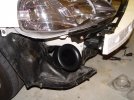
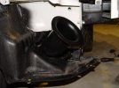
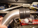
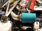
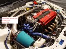
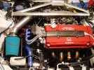
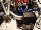
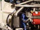
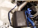
Now we go on to install the 2nd part of the ICE BOX... the velocity stack arm.
You can aim the tip however you like... Comptech suggests 'as forward as possible' or aim upwards for water concerns. I aimed mine at 45degrees.
(I didn't want to much dirt getting through since I have a cut-out foglight slot on my facelift bumper. I'll be realigning it straight forwards when I change my front end back to its original Pre-facelift.)

Ok, My final intake is here. My DIY Installation instructions should help those who have bought 2nd hand items since these are no longer in production. Although to this date, there are still a handful of NEW items left.
In short, the reason I chose this intake was for its efficiency, quieter and clean subtle stock look. The system also makes use of 2 velocity stacks.
It is a 3.5" system throughout from the polished intake arm to the end of the ICE BOX which has a 5.5" velocity flare. Theres also an extra velocity stack that acts as a frame for the filter to tighten over. The filter is also quite big. A bit bigger than the stock DC2R.
For best results, the polished Comptech aluminium intake arm should be used instead of the stock rubber arm, simply because the aluminium arm is smooth. The stock rubber arm has ripples inside the arm which in theory, affects flow. looking at the kit, Comptech really put lots of engineering into this intake.
I'll start with removing your old intake system. It is also manatory that you remove your front bumper for this install. It will also make things easy if you remove your front strut bar.
This is the kit;
Now I will label the brackets for the ICE BOX as #1,#2 and #3.
We will start by installing Bracket #3
Look down next to the bottom of your radiator and hose.
You will see 3 large bolts tied down on the left wall.
Remove the one closest to the tranny to install the bracket #3
BUT, do not tighten the bolt, leave it loose as you will need to align it later before tightening.
Like this...
After that, we will install Bracket #2
Undo the tranny engine mount bolt that bolts to the side
Install the bracket and DO NOT tighten the bolt, just hand tight for now.
You will need to align the bracket angle later on.
Like this...
Next we install the last bracket #1
There should be a threaded hole here
Install the bracket and again, just hand tighten the bolts for later alignment.
like this...
Once done it should look like this...
Now we fit the ICE BOX in to see how it aligns with the brackets...
Bracket #2 will need to be aligned at 45degrees facing you for the ice box to fit.
Once the ICE BOX has sat on, dont bolt anything down yet.
Carefully the slowly take off the ICE BOX not to upset the Bracket #2s angle.
Fully tighten the bolt for Bracket #2 like this...
Put back the ICE BOX...
Hold down the ICE BOX by fully tightening the bolts with washers on Bracket #1 and #2 like this...
Then fully tighten the bolt to the chassis on Bracket #1.
Now we go on to install the 2nd part of the ICE BOX... the velocity stack arm.
You can aim the tip however you like... Comptech suggests 'as forward as possible' or aim upwards for water concerns. I aimed mine at 45degrees.
(I didn't want to much dirt getting through since I have a cut-out foglight slot on my facelift bumper. I'll be realigning it straight forwards when I change my front end back to its original Pre-facelift.)
Attachments
-
 $DSC03080.JPG162.9 KB · Views: 6,714
 -
 $DSC03081.JPG142.1 KB · Views: 5,563
 -
 $DSC03082.JPG124.9 KB · Views: 5,327
 -
 $DSC03083.JPG110.9 KB · Views: 5,387
 -
 $DSC03084.JPG166.6 KB · Views: 5,319
 -
 $DSC03098.JPG94.6 KB · Views: 5,095
 -
 $DSC03115.JPG115.1 KB · Views: 5,670
 -
 $DSC03113.JPG123.6 KB · Views: 5,191
 -
 $DSC03093.JPG181.5 KB · Views: 5,814
 -
 $DSC03085.JPG157.7 KB · Views: 5,973
 -
 $DSC03105.JPG105.7 KB · Views: 5,000
 -
 $DSC03103.JPG124.4 KB · Views: 5,082
 -
 $DSC03102.JPG118 KB · Views: 5,026
 -
 $DSC03101.JPG109.4 KB · Views: 5,074
 -
 $DSC03099.JPG90.6 KB · Views: 5,168
 -
 $DSC03116.JPG132.6 KB · Views: 5,032
 -
 $DSC03110.JPG141.9 KB · Views: 5,131
 -
 $DSC03109.JPG116.6 KB · Views: 5,061
 -
 $DSC03106.JPG151.7 KB · Views: 5,170
 -
 $DSC03117.JPG137.4 KB · Views: 5,447
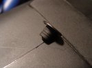
 where did you get the plug that blocks the intake sensor?
 so I better keep my mouth shut...
